Mold Manufacture Technique of Permanent Magnetic Arc Ferrite
As an important part of magnetic materials, permanent ferrite materials play an important role in the electronics industry, information industry, motorcycle, power tool industry, automobile industry and other industries with their high cost performance. The permanent magnet ferrite magnetic tile used in the permanent magnet DC motor is widely used.
Wide use and high added value are sought after at home and abroad.
The main processes of a permanent ferrite magnet tile manufacturing plant generally include: material making, forming, sintering, grinding, cleaning, inspection and packaging and other processes. The most important and most difficult of these processes is the molding process, and the most important of the molding process is the manufacture of the mold, which is the basis and difficulty of press molding.
Due to the high-strength magnetic field in the working environment of this mold for the orientation of the slurry, it is easy to cause uneven density distribution of the blank during press molding, resulting in a large internal stress of the blank after sintering, and finally causing a large number of product fractures. , Therefore, the manufacture of molds determines the production efficiency and product pass rate to a large extent.
As the premier carbide dies supplier, PTJ knows the many benefits behind carbide dies machining and powder metallurgy mold. Carbide dies is known for being the best electronic product mold manufacturing method while having a relatively low cost. PTJ professionals find that Die machining is a smooth, easy process because carbide is a good die machining material that is easy to long life.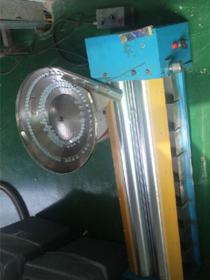
Table of Contents
Carbide Dies Design
When designing the mold, the size of the blank must be determined first. The size of the blank is determined on the basis of the product size in consideration of the amount of grinding and the size enlargement factor. The size magnification factor refers to the ratio of a certain size of the formed blank before sintering to the corresponding size after sintering (referred to as the scaling factor).
The scaling factor is the basis for designing the size of each part in the mold. From the size of the blank, combined with the nominal pressure tonnage of the press and the length and width of the working table, the number of cavities used in the mold can be determined. There are many factors that affect the scaling factor. For tile-shaped magnets, it is also related to the size of the magnet and whether it is oriented radially or in parallel along the axis of symmetry.
For the radial orientation along the radial direction, as an example, when the inner diameter of the magnet tile is sintered, the inner diameter is ground from the inside to the outside, and the outer diameter is ground from the outside to the inside, and the length is not ground. The scaling factor of the outer diameter is 1.302, and the scaling factor of the inner circle is 1.294, so it is an inevitable phenomenon that a certain stress will be generated inside the magnet during sintering.
At present, wet pressing generally adopts the molding method of injection slurry, floating pressing, and pull-down demoulding. The pressing method of this molding should be single-sided pressing. The upper mold of the mold is a whole, and the upper mold is wrapped with a layer of filter cloth and covers the concave mold. The concave mold may contain one or several cavities. The lower mold is fixed during forming. When the upper mold descends to contact and compress the concave mold surface and close the concave mold, the magnetizing magnetic field is started immediately, and the slurry is injected into the mold pool from the injection hole by the injection pump, and then It enters into the cavity through the feeding trough of the die, and then starts to pump water, so that the water in the slurry is discharged through the water pumping hole on the upper die surface of the filter cloth. After the slurry is filled into the cavity, the upper mold and the concave mold are lowered synchronously to seal the injection slot, and the excess material is returned to the material pool, so that the powder in the concave mold is formed to form a blank. After forming is demagnetized, the concave mold continues to descend to expose the blank, the upper mold rises, the blank is removed, and then the concave mold is reset to complete a molding cycle.
In addition, there are other molds that are different from this injection system. For example, some manufacturers use runner injection molds, but the design of the main parts of the mold is the same, which will be explained below.
Upper Mold (Doubles As Absorbent Board)
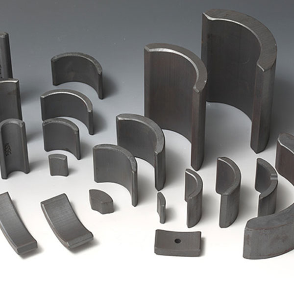
There are two different orientations of tile magnets. One is radially oriented along the radial direction, and the magnetic flux density distribution is saddle-shaped when measured along the inner arc surface of the magnetic tile. The other is oriented in parallel along the axial direction. If measured along the inner arc surface of this magnetic tile, the magnetic flux density distribution is sinusoidal. After these two kinds of magnets are installed into a motor, the former has a higher magnetic energy utilization rate of about 20% than the latter, but the latter has a relatively stable rotor rotation and less jitter. For permanent magnet users, the former is more inclined. When forming this kind of magnet, the forming part should be at the upper part of the cavity (the forming coil is around the die), close to the upper end surface of the forming magnetic field coil, so that the divergent magnetic field can be used to orient the magnetic powder. In addition, the upper mold drills radial suction holes, as shown in Figure 3. Because the slurry is arranged in chains along the direction of the magnetic field under the action of the magnetic field, the chain-like arrangement of the slurry will be radially arranged under the action of the radial suction hole suction. In this design, the outer arc of the magnet tile faces upwards to make full use of the forming magnetic field. The magnetic flux density of the formed magnet tile and inner arc is higher than that of the outer arc, which also meets the requirements of use. Generally, the thickness of the magnet tile is not large, so single-sided water absorption can be used, that is, a vacuum suction hole is designed on the upper mold, which can avoid the damage of the arc surface of the magnet tile due to the water absorption hole, and maintain the surface finish at a certain level , In order to reduce the amount of grinding during grinding.
The upper mold material can be 20 steel, which is a low-carbon steel (with a carbon content of less than 0.25%), and it is also a high-quality carbon steel in the classification of steel. The steel not only guarantees the chemical composition, but also the mechanical strength, and the magnetic permeability is high.
45 steel (GB) has better mechanical strength than 20 steel (GB), but due to its high carbon content and large coercive force, its permeability is lower than that of 20 steel. The manganese content of 20 steel is in the normal range and is often supplied as hot-rolled steel. At this time, the hardness is ≤156HB (while 45 steel is 241HB). Due to the low manganese content, the plasticity, toughness, and weldability are good, and the cold deformation performance is excellent. In order to overcome the lack of mechanical strength, surface carburizing treatment is often used. The thickness of the carburized layer can be up to 1.5mm. After carburizing, it is quenched. The quenching temperature is 800~830℃, and then tempered at low temperature, the hardness can reach 60~62HRC, so that the upper mold surface High hardness and enhanced wear resistance.
Lower Mold
Concave Mold
The slurry in the cavity of the wet-pressed tile-shaped mold is injected into the concave mold cavity from the slot of the injection groove. The injection groove is formed on the die. The distance between the injection groove and the upper end surface of the cavity is designed to be related to the speed of the slurry entering the cavity and the moisture content. Generally, 1.5 times the thickness of the blank is appropriate. When designing the cavity There should be about 2° demoulding taper (drawing degree). The ideal material for the cavity mold is with or without magnetic hard alloy. The cavity mold made of this material has a long service life, a high degree of roughness and a high pass rate. In addition, it can be used as a concave mold material:
- ①18-8 stainless steel;
- ②High-strength austenitic non-magnetic die steel (7Mn15Cr2Al3V2WMo);
- ③High manganese-vanadium non-magnetic die steel;
- ④50Mn18Cr4VA non-magnetic die steel;
- ⑤Ti alloy die steel;
- ⑥GH36GX non-magnetic die steel.
The composition, heat treatment, production process, physical properties, and mechanical properties of GH36GX non-magnetic corrosion-resistant steel used as die materials are as follows:
- ① Composition design and heat treatment. The composition (%) is: C: 0.50 to 0.65, Si: 0.30 to 0.80, Mn: 11.00 to 13.00, P ≤0.060, S≤0.030, Cr: 12.00 to 14.00, Ni: 3.00 to 4.00, V: 1.30 to 1.80. The steel uses C, Mn, and Ni to austenitize the steel, uses Cr and Ni to obtain corrosion resistance, uses VC as the age hardening phase, and uses solid solution and aging for the heat treatment of the steel. The solid solution at 1150°C can make a large amount of carbides Dissolved into austenite, aging at 670℃ can obtain the VC phase of the best size, which makes the steel obtain high hardness. The specific heat treatment system adopted is as follows: 1150℃×2h water quenching +670℃×16h air cooling. The important reason for choosing VC as the hardening phase is that the phase is a non-magnetic phase of FCC crystal type;
- ② Production process. The alloy can be smelted in a non-vacuum induction furnace or an electric arc furnace. The tapping temperature is controlled at 1530℃±15℃, and the pouring temperature is 1460℃±20℃. It is poured in a sand mold. The steel contains high C and Mn, and has high fluidity. Good, suitable for casting, but pay attention to the feeding operation, otherwise the casting is prone to shrinkage;